A ne5532 audio preamplifier circuit diagram plotted by this system Microphone ne5532 preamplifier preamp eleccircuit pcb amplifier massager How to make low pass filter for subwoofer with ne5532 ic
A NE5532 audio preamplifier circuit diagram plotted by this system
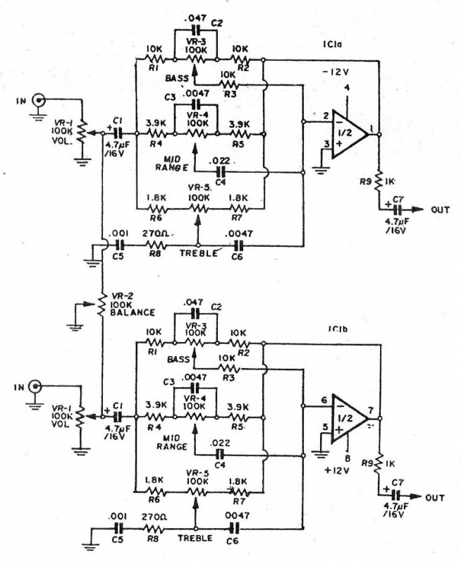
Tone control circuit circuits ne5532 bass treble mid ic using guitar diagram audio amplifier stereo schematics schematic preamp amp board
Ne5532 low noise amplifier circuit diagram 2
Asymmetric pre-amplifier circuitNe5532 power amplifier circuit diagram Lm4766+ne5532 package 2x40w amplifier circuitNe5532 filter pass low circuit high diagram output amplifier audio subwoofer board gain frequency diy choose.
Ne5532 circuit preamplifier amplifier plottedFilter pass low subwoofer ne5532 ic diy make Pic.2 schematicNe5532 circuit diagram amp amplifier op power ic schematic forum eevblog headphone diagrams simple.

Amp ne5532 pcb
Ne5532 preamplifier circuit diagram : 3 : mini electric massagerPre supply single amp audio circuit preamplifier amplifier power gr next circuits How to make 3 band tone control circuits with op-amp ne5532 ic withoutNe5532 amplifier circuit diagram noise low seekic below.
Ne5532 high and low pass output filter circuit .


